ANSI ACCREDITED STANDARDS COMMITTEE C63
ELECTROMAGNETIC COMPATIBILITY
SUBCOMMITTEE 8 – MEDICAL DEVICES AND EMC
Minutes
Tuesday –
IEEE
Headquarters –
1 Opening
and Self-Introductions
Members Present Affiliation
Matthew
Bakke
Stephen Berger TEM Consulting
Bob DeLisi UL
Gerard Hayes Sony Ericsson
Don Heirman Don Heirman Consultants
George Hirvela Cingular
Bob Hofmann Hofmann EMC Engineering
Dan Hoolihan Hoolihan EMC Consulting
William Hurst FCC
Bob Jenkins Welch Allyn
Victor Kuczynski Vican Electronics
Harry Levitt Hearing Loss Association
Dheena Moongilan Lucent
Joe Morrissey Motorola
Werner Schaefer Cisco
Jeff Silberberg FDA
Jim Turner ATIS
Steve Whitesell Telecommunications Industry Assoc.
Al Wieczorek Motorola
Dave
Zimmerman TUV
Guests Affiliation
Poul Andersen SAE
Colin Brench HP
Kendra
Green Samsung
Telecom
Ed Hare American Radio Relay League
Warren Kesselman Independent
Richard Worley Dell
Al Wieczorek asked to confirm a quorum. It was confirmed by the chair that 17 members were present out of a total of 31 members so a quorum was present.
2 Review
and Adoption of Agenda
The DRAFT Agenda was reviewed and adopted. See Attachment 1.
3. Review
and Adoption of Minutes of Previous Meeting
Jeff
Silberberg Moved to approve the Draft Minutes of the
4. Working
Group Reports
4.1 WG#1 – Jeff Silberberg - C63.18
Working Group 1 is developing the Second Edition of C63.18. Jeff Silberberg, the working group chair, reported that progress continues at a slow rate.
The Second Edition will use a field-strength meter as the principal instrument for measuring fields from cellular sources. The working group has requested information from Dave Baron of ETS-Lindgren, relative to measurement of peak field-strength (e.g., from cell phones) with field strength sensors. It was pointed out by Steve Berger that there is an excellent article on power probe sensors in the latest issue of Evaluation Engineering.
4.2 WG#2 – Bob DeLisi – C63.21
Bob DeLisi from UL is chairing this group and looking for new members. Bob gave a brief review of the history of the project Jeff Silberberg accepted an action item to recruit members from the FDA for the Working Group.
4.3 WG#3 – Steve Berger – C63.19
Steve Berger reviewed the history
of C63.19 and also reported on the recent progress of this working group. Two
meetings of the Working Group have been held in the last two months; both
meetings were held at the FCC Lab in
A protracted discussion took place about the latest Draft Amendment of the standard. Concerns were expressed by ATIS on some of the wording implemented in the latest proposed amendment.
Steve Berger proposed a Motion to “Recommend to the Main C63 Committee to adopt the amendment including two issues recently added through electronic mail.”
The Motion was seconded. After extensive discussion, some members had trouble with the wording of several sections of the amendment.
It was agreed to attempt to resolve the wording issues with the Amendment during the meeting. A subgroup of people worked in real time to make wording changes. Agreement was reached on new wording.
A Motion was then made by Steve Berger to amend the original Motion to include the wording changes for Step 10, Step 12, and clause 7.3.3. The Amendment was seconded and discussed. The Motion to Amend the Original Motion was voted on and passed with 15 positive votes, no negative votes and 2 abstentions (Bill Hurst – FCC, Werner Schaefer – Cisco Systems).
The Amended Motion was then voted on by a Roll Call Vote and it was passed unanimously by the Subcommittee with 17 ayes, no negatives and 3 abstentions. The 17 ayes were Matthew Bakke, Stephen Berger, Bob DeLisi, Gerard Hayes, Don Heirman, George Hirvela, Bob Hofmann, Dan Hoolihan, Bob Jenkins, Victor Kuczynski, Harry Levitt, Joe Morrissey, Jeff Silberberg, Jim Turner, Steve Whitesell, Al Wieczorek, and Dave Zimmerman. The three abstentions were Bill Hurst – FCC, Werner Schaefer – Cisco Systems, and Dheena Moongilan – Lucent Technologies.
Stephen Berger provided a file listing the complete set of changes approved, “C6319 - Proposed Amendment - 060314.pdf”. See Annex to these minutes for a complete listing of the changes approved for the amendment.
5
Unfinished
Business
Due to a lack of time, no discussion was held of Unfinished Business.
5.1 IEC SC62A Maintenance Team
23 – Jeff Silberberg
IEC SC62A MT23 Report for C63 SC8 Meeting March 2006
·
Meeting 7-10 February,
· Third edition of IEC 60601-1, basic safety and essential performance of medical electrical equipment and medical electrical systems, has been approved and published
· Draft third edition of IEC 60601-1-2 circulated for ballot
o IEC 62A/522/CDV
o Editorial changes only – alignment with third edition of IEC 60601-1
o Ballot closes 7 July
· Plans for fourth edition of IEC 60601-1-2 circulated to SC62A for comment
o Requirements for electromagnetic phenomena
o IEC 62A/509/DC
o Approved by SC62A
o Comments received and addressed
o Will be circulated shortly to National Committees as a maintenance cycle report
o European members of MT23 will meet to further the work on requirements for electromagnetic environments other than general hospital
· Standard for EMC (performance) of medical electrical equipment and systems in development
o Will be proposed as a new work item
o IEC SC62A MT23 will be proposed to do the work
o Will be synchronized with the fourth edition of 60601-1-2
o Will include a guide to the use of both 60601-1-2 and the new standard
· Corrigendum to IEC 60601-1-2 Edition 2.1 (clarification that battery-operated medical equipment may be labeled as suitable for domestic establishments) delayed
o MT23 plans to submit the corrections as comments on the CDV
·
Next meeting October 2006,
5.2 AAMI/EMC Committee Report
No report
5.3 FDA Report – Jeff Silberberg
FDA Report for C63 SC8 Meeting March 2006
- Lab activities
- Continue work with TSA on medical device EMC with security systems, metal detectors
- Continue development of metal detector simulator for medical device immunity testing
- Continue lab project to investigate medical devices and wireless technology (Bluetooth, 802.11 b) EMC and data integrity concerns
- MRI implant heating computational methods and lab testing with ASTM group
- Standards activities
- C63: C63.19 revision, editing C63.16
- IEC SC62A MT 23
- Revision of supplementary information pages for IEC and ANSI/AAMI/IEC 60601-1-2 posted on CDRH website
i. Recognition of Amendment 1
ii. Provide evidence of meeting the labeling requirements
iii. Transition to Amendment 1 / Ed. 2.1, withdrawal of Ed. 2 without A1
iv. Presenting on IEC 60601-1-2 at AAMI conference on third ed. 60601-1
· 22-24 May
- Work in IEEE 1073/ISO TC 215 Wireless technology deployment: information and guidance
- ISO TC 150 SC on implanted infusion pumps, implanted neurostimulators.
i. Method to create 150 A/m (level suggested in ISO 14708-1) completed
- ISO TC 173 SC 1 on ISO 7176 wheelchair standards
- AAMI EMC committee revision of TIR 18
- Participating in work group on test methods for 802.11 equipment
- CDRH outreach
- CDRH guidance for wireless technology in and around medical devices soon to be circulated for comment
i. Concerns for:
· performance of wireless functions
· wireless coexistence
· wireless quality of service
· integrity of data transmitted wirelessly
· security of data transmitted wirelessly and wireless network access
· EMC
- Presenting on wireless in and around medical devices at AAMI Conference and Expo, June 2006
- Coordination and meeting with FCC re: medical device concerns
i. Hearing aids
ii. FCC initiative on wireless medical technology and expansion of the Medical Implant Communications Service (MICS – for implants)
iii. Medical telemetry, including WMTS
iv. BPL
v. Approvals
5.4
Mobile
Healthcare
No report.
6
New Business
It was moved by Steve Berger to nominate Joe Morrissey as Vice-Chair of Subcommittee 8. The Motion was seconded and discussed. The Motion was approved with one abstention.
7
Next Meeting
The
next meeting will be
ANNEX
Draft Language For:
2006 Amendment
to
ANSI C63.19-2006
(final draft 3.12)
Overview
This document
provides the proposed language addressing the six points of the PINS to develop
an amendment to ANSI C3.19-2006. The
scope of this effort, as listed in the PINS is:
“The following sections will be addressed
in the currently published standard C63.19:
a)
Change
the magnetic measurement orientations from Axial and two radial to two
measurements in one plane (reference Section 6.3, and 7.3.3, Annex A-3)
b)
Determine
the signal strength(s) for the new T-coil measurement orientations (Section 7.3.1)
c)
Revise
the Signal to Noise range in table 7.7
d)
Decouple
the overall RF measurement on the mobile from limiting the rating of the T-coil
measurement
e)
Change
the RF measurement position from bottom of probe to the center of element and
change to test distance from 1 cm to 1.5 cm (reference Section 4.4, and Annex A-2)
f)
Incorporate
TVC (test validation coil) tool into the
Standard as an illustrative reference (similar to the dipole in the RF) in the
T-coil Section 6 and the Annex (for development). The TVC’s intended use
is as a magnetic source for measurement setup validation, to be specified as an
open-sourced device. It is not intended
as a substitute for Helmholtz coil calibration of the magnetic sensing probe.”
Table of Contents
Issue A – Reduction to 2 measurement orientations
Issue B – Required signal strength
2nd Change – Clause 6.4.2 at the end of
¶ 1
3rd Change – Clause 7.3.2 captions for
Figures 7-1 & 7-2
1st Change – Clause 7.3.3 Table 7.7
3rd Change – Clause 6.3.1 Step 2
4th Change – Clause 6.3.4.1 ¶ 2
5th Change – Clause 6.3.4.2 ¶ 1 sentence
2
6th Change – Clause 6.2.1 ¶ 2 sentences
2 & 3
7th Change – Clause 6.4.1 Step 7
Issue D – Decouple the RF from the T-Coil rating
1st Change – Clause 6.3.1 last 
2nd Change – Clause 7.3.3 ¶ 3 & 4
4th Change –Clause 4.4.1.2.1 Step 10
5th Change –Clause 4.4.1.2.2 Step 12
Issue E – Change the measurement distance
1st Change – Section 4.3.2.1 ¶ 4 Bullet 4
2nd Change – Section 4.3.2.1.1 ¶ 1 Bullet 3
3rd Change – Section 4.3.2.1.3 ¶ 1
4th Change – Remove figure 4-2 & 4-3
5th Change – Section 4.4 ¶ 2 Line 6
6th Change – Section 4.4 ¶ 6 Line 1
7th Change – Section 4.4 ¶ 6 Line 5
8th Change – Section 4.4 ¶ 8 Bullet 2
9th Change – Section 4.4.1.2.1 Step 2
12th Change – Annex A.2 Bullet 4
13th Change – Annex A.2 Figure A-2
14th Change – Annex A.2.1 Figure A-3
15th Change – Annex A.2.1 Figure A-4
16th Change – Section 4.3.2.1 Table 4-2
5th Change – Add new Clause D.19
Summary of changes
|
Summary of
Changes |
|
|
Issue |
Summary of
Changes |
|
a) Change the magnetic measurement orientations
from Axial and two radial to two measurements in one plane (reference Section
6.3, and 7.3.3, Annex A-3) |
Rejected. Retain current measurement orientations. |
|
b) Determine the signal strength(s) for the new
T-coil measurement orientations (Section 7.3.1) |
Adopt -18 dB A/m
as the required signal level for all orientations. |
|
c) Revise the Signal to Noise range in table
7.7 |
Proposal adopted
with 20 dB as the Category 2/3 boundary and other categories boundaries
spaced 10 dB apart. The use of AWF was
removed from table 7-7. The use of A-weighting in measuring noise was
retained. Implementing wording is
contained in this document. |
|
d) Decouple the overall RF measurement on
the mobile from limiting the rating of the T-coil measurement |
Proposal adopted
to allow separation of RF (emission) M and T rating IF the M rating (the
lower of M or T) is greater than or equal to M3. Such that a phone rated at
M3 and T4 would be acceptable; where the T4 rating is for baseband only. |
|
e) Change the RF measurement position from
bottom of probe to the center of element and change to test distance from 1 cm
to 1.5 cm (reference Section 4.4, and
Annex A-2) |
Adopt per
specific wording changes recorded in this document. |
|
f)
Incorporate
TVC (test validation coil) tool into the Standard as an illustrative
reference (similar to the dipole in the RF) in the T-coil Section 6 and the
Annex (for development). The TVC’s intended use is as a magnetic source
for measurement setup validation, to be specified as an open-sourced device. It is not intended as a substitute for
Helmholtz coil calibration of the magnetic sensing probe.” |
Adopt per
specific wording changes recorded in this document. |
|
|
|
Issue A – Reduction to 2 measurement orientations
“Change the magnetic measurement orientations from Axial and two radial to two measurements in one plane (reference Section 6.3, and 7.3.3, Annex A-3)”
Proposed change was rejected. The current wording of the standard remains.
Issue B – Required signal strength
“Determine the signal strength(s) for the new
T-coil measurement orientations (Section 7.3.1)”
The WG decided to move to a single value on the T-Coil
signal strength requirement.
1st Change - Clause 7.3.1
From:
7.3.1 T-Coil coupling field intensity
The T-Coil signal from the WD, when measured as specified in this standard, shall meet the parameters set forth below for the axial field intensity and the radial field intensities. These measurements shall be made with the WD operating at a reference input level as defined in 6.3.2.1.
These levels are designed to be compatible with hearing aids that produce the same acoustic output level for either an acoustic input level of 65 dB SPL or a magnetic input level of –25 dB (A/m) (56.2 mA/m)[1] at either 1.0 or 1.6 kHz. The hearing aid operational measurements are performed per ANSI S3.22.
The axial component of the magnetic field, directed along the measurement axis and located at the measurement plane, shall be ³ -13 dB (A/m) at 1 kHz, in 1/3 octave band filter.
7.3.1.2 Radial field intensity
The radial components of the magnetic field, as measured at the radial measurement points described in Section A.3[2], shall be ³ -18 dB (A/m) at 1 kHz, in 1/3 octave band filter.
To:
7.3.1 T-Coil coupling field intensity
The T-Coil signal for all orientations, when measured as specified in this standard, shall be ³ -18 dB (A/m) at 1 kHz, in a 1/3 octave band filter. These measurements shall be made with the WD operating at a reference input level as defined in 6.3.2.1.
These levels are designed to be compatible with
hearing aids that produce the same acoustic output level for either an acoustic
input level of 65 dB SPL or a magnetic input level of –25 dB (A/m) (56.2 mA/m)[3] at
either 1.0 or 1.6 kHz. The hearing aid
operational measurements are performed per ANSI S3.22.
2nd Change – Clause 6.4.2 at the end of ¶ 1
From:
…. 7.3.1.1 for the axial reading and Section 7.3.1.2 for the radial readings.
To:
…. 7.3.1.
3rd Change – Clause 7.3.2 captions for
Figures 7-1 & 7-2
From:
Figure 7 1 - Magnetic field frequency response for WDs with a field between -10 to -13 dB (A/m) at 1 kHz
Figure 7 2 - Magnetic field
frequency response for WDs with a field that exceeds -10 dB(A/m) at 1 kHz
To:
Figure 7 1 - Magnetic field frequency response for WDs with a field ≤ -15 dB (A/m) at 1 kHz
Figure 7 2 - Magnetic field frequency response for WDs with a field that exceeds -15 dB(A/m) at 1 kHz
Issue C – Revise table 7.7
“Revise
the Signal to Noise range in table 7.7”
1st Change – Clause 7.3.3 Table 7.7
From:
|
Category |
Telephone
parameters WD signal
quality ((signal + noise)-to-noise ratio in dB) |
|
|
|
AWF = 0 |
AWF = -5 |
|
|
Category T1 |
|
|
|
Category T2 |
-10 to 0 dB |
|
|
Category T3 |
0 to 10 dB |
5 to 15 dB |
|
Category T4 |
> 10 dB |
>15 dB |
|
|
|
|
|
(NOTE: For cases where it can be shown that the audio-band interference is not dominated by the RF pulse rate of the phone, AWF does not apply) |
|
Table 0‑1 – T-Coil signal quality categories
To:
|
Category |
Telephone
parameters WD signal
quality (signal-to-noise ratio in dB) |
|
|
|
|
Category T1 |
0 to 10 dB |
|
Category T2 |
10 to 20 dB |
|
Category T3 |
20 to 30 dB |
|
Category T4 |
>30 dB |
|
|
Table 0‑2 – T-Coil signal quality categories
2nd Change – Clause 6.3.1
From:
The following summarizes the basic test flow:
To:
The following steps summarize the basic test flow for determining ABM1 and
ABM2. These steps assume that a sine
wave or narrowband 1/3 octave signal can be used for the measurement of
ABM1. An alternate procedure yielding
equivalent results utilizing a broadband excitation is described 6.4.
3rd Change – Clause 6.3.1 Step 2
From:
2. Set the reference drive level for the system with the maximum volume control setting or as specified by the manufacture. The drive level is set such that the reference input level defined in Section 6.3.2.1 is input to the base station simulator (or manufacturer’s test mode equivalent) in the 1 kHz, 1/3 octave band. This drive level shall be used for the T-Coil signal test (ABM1 at f ). Either a sine wave at 1025 Hz or a voice-like signal as defined in Section 6.3.2 shall be used for the reference audio signal. If interference is found at 1025 Hz an alternate reference audio signal frequency may be used. The same drive level will be used for the ABM1 frequency response measurements at each 1/3 octave band center frequency.
To:
2. The drive level to the WD is set such that the reference input level defined in Section 6.3.2.1, Table 6-1 is input to the base station simulator (or manufacturer’s test mode equivalent) in the 1 kHz, 1/3 octave band. This drive level shall be used for the T-Coil signal test (ABM1) at f = 1 kHz. Either a sine wave at 1025 Hz or a voice-like signal, band-limited to the 1 kHz 1/3 octave, as defined in Section 6.3.2, shall be used for the reference audio signal. If interference is found at 1025 Hz an alternate nearby reference audio signal frequency may be used.[4] The same drive level will be used for the ABM1 frequency response measurements at each 1/3 octave band center frequency. The WD volume control may be set at any level up to maximum, provided that a signal at any frequency at maximum modulation would not result in clipping or signal overload.
4th Change – Clause 6.3.4.1 ¶ 2
From:
A 1025 Hz ± 10 Hz signal is recommended for sine test signals for the signal quality measurements. For voice-like test signals, such as ITU P-50 artificial speech, the speech should be band-limited to the 1/3 octave centered at 1025 Hz….
…. The voltage required to produce this level (in dBm0) in the 1025 Hz band should be maintained for T-Coil signal measurements at all frequencies for the frequency response measurement.
To:
A 1025 Hz ± 10 Hz signal is recommended for sine test signals for the signal quality measurements. For voice-like test signals, such as ITU P-50 artificial speech, the speech should be band-limited to the 1/3 octave centered at 1 kHz….
…. The same reference input level should be maintained for T-Coil signal measurements at all the other frequency bands for the frequency response measurement.
5th Change – Clause 6.3.4.2 ¶ 1 sentence 2
From:
These measurements are made over
the frequency range of 300 to 3000 Hz either in 1/3 octave bands centered at
the ISO 266 R10 series of standard test frequencies or using a broadband signal
that is subsequently analyzed for frequency content.
To:
These measurements are made over
the frequency range of 300 to 3000 Hz either in 1/3 octave bands centered at
the ISO 266 R10 series of standard test frequencies (as described in Section
6.3) or using a broadband signal that is subsequently analyzed for frequency
content (as described in Section 6.4).
6th Change – Clause 6.2.1 ¶ 2 sentences 2
& 3
From:
For the measurement of ABM1, this
criterion applies in each 1/3 octave band over the specified voiceband. For the measurement of ABM2, this criterion
applies over the full measurement bandwidth.
To:
For the measurement of ABM1 (Audio Band Magnetic signal – desired), this criterion applies in each 1/3 octave band over the specified voiceband. For the measurement of ABM2 (Audio Band Magnetic signal – undesired), this criterion applies over the full measurement bandwidth.
7th Change – Clause 6.4.1 Step 7
From:
Measure desired plus undesired
audio band magnetic signals, ABM1.
To:
Measure audio band magnetic
signal, ABM1.
Issue D – Decouple the RF from the T-Coil rating
“Decouple
the overall RF measurement on the mobile from limiting the rating of the T-coil
measurement”
The
committee adopted a proposal to allow separation of RF (emission) M and T
rating IF the M rating (the lower of M or T) is greater than or equal to M3.
Such that a phone rated at M3 and T4 would be acceptable; where the T4 rating
is for baseband only.
1st Change – Clause 6.3.1 last 
Remove
the last paragraph:
To assure that the desired signal quality is provided, the RF field intensity
at this measurement point must be at or below that required for the assigned
category. If the RF field intensity
measurement at the location of the axial measurement of the desired signal
(ABM1) was not recorded in the 5 x 5 cm scan taken per Section 4, then measure
the RF field intensity at this location.
The RF field intensity at this location shall be at or below that
required by the assigned category.
2nd Change – Clause 7.3.3 ¶ 3
& 4
Remove 
3 & 4 from Clause 7.3.3:
A device is assessed beginning by determining the category of the RF
environment in the area of the T-Coil source. The RF measurements made for the
T-Coil evaluation are used to assign the category from Section 7.2, category T1
through T4. This establishes the RF environment presented by the WD to a
hearing aid. If the device meets the additional requirements of this section it
qualifies for the T designation, T1 through T4.
A device may be classified according to its audio coupling mode (M1 through M4), its T-Coil mode (T1 through T4), or both. Note: the T mode rating may be higher than the M mode rating.
3rd Change – New Clause 7.3.3
Add new
Clause 7.3.3:
This section describes the relationship between the M rating, which is based on
the RF emission tests performed in Clause 4 and the T rating, which is based on
the T-Coil tests performed in Clause 6.
If the WD meets an M3 or M4 rating for both microphone and T-Coil mode, per Clause 4, it becomes a candidate for the T designation (see 7.3.4). A WD is assessed by determining the category of the RF environment in the area of the T-Coil source. This establishes an acceptable RF environment presented by the WD to a hearing aid T-Coil.
4th Change –Clause 4.4.1.2.1 Step 10
From
Repeat steps 1-9 for the T-Coil mode assessment. The grid
shall be shifted so that it is centered on the axial measurement point. Both
the E- and H-field are measured for this grid. The category, per the tables in
Section 7.2, obtained in step 8 for either E- or H-field determines the T
category for the T-Coil mode assessment. Record the WD category rating.
To
For the
T-Coil mode assessment repeat steps 1-9. The grid shall be shifted so that it
is centered on the axial measurement point. Both the E- and H-field are
measured for this grid. The category, per the tables in Section 7.2, obtained
in step 8 for either E- or H-field determines the T category for the T-Coil
mode assessment. Record the WD category rating.
If the
axial measurement point is contained in a non-excluded sub-grid of the first
scan, then a second scan is not necessary.
The first scan may be used for the microphone and T-Coil
assessment.
5th Change –Clause 4.4.1.2.2 Step 12
From
If the center of the T-Coil location is in a different
position from the speaker opening, repeat steps 1-11 for the T-Coil mode
assessment. The grid shall be shifted so
that it is centered on the axial measurement point. Both the E and H-Field are measured for this
grid. The lowest category, per Table 7 4
or Table 7 5, obtained in step 11 for either E or H-Field determines the T
category for the T-Coil assessment.
Record the WD category rating.
To
For the
T-Coil mode assessment repeat steps 1-11. The grid shall be shifted so that it
is centered on the axial measurement point. Both the E- and H-field are
measured for this grid. The category, per the tables in Section 7.2, obtained
in step 11 for either E- or H-field determines the T category for the T-Coil
mode assessment. Record the WD category rating.
If the
axial measurement point is contained in a non-excluded sub-grid of the first
scan, then a second scan is not necessary.
The first scan may be used for the microphone and T-Coil assessment.
Issue E – Change the measurement distance
“Change
the RF measurement position from bottom of probe to the center of element and
change to test distance from 1 cm to 1.5 cm
(reference Section 4.4, and Annex A-2)”
1st Change – Section
4.3.2.1 ¶ 4 Bullet 4
From:
The probe-to-dipole separation,
which is measured from top surface of the dipole to the nearest point on the
probe sensor element, should be 10 mm, as shown in Figures C-3 and C‑4.
To:
The probe-to-dipole separation,
which is measured from top surface of the dipole to the center point of the probe
sensor element, should be 10 mm, as shown in Figures C-3 and C-4.
2nd Change – Section
4.3.2.1.1 ¶ 1 Bullet 3
From:
the probes are 10 mm from the surface of the dipole elements.
To:
the center point of the probe
elements are 10 mm from the surface of the dipole elements.
3rd Change – Section
4.3.2.1.3 ¶ 1
From:
The probe is positioned over the illuminated dipole at
10 mm distance from the nearest point on the probe sensor element to the top
surface (edge) of the dipole element as shown in Section C.4.3.
To:
The probe is positioned over the illuminated dipole at 15 mm distance from the center point of the probe sensor element to the top surface (edge) of the dipole element as shown in Section C.4.3.
4th Change – Remove
figure 4-2 & 4-3
From:
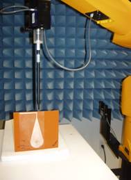
Figure 0‑1 – Planar dipole setup
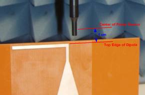
Figure 0‑2 – Probe distance from planar dipole
To:
{Figures removed the distance is
inaccurate and IEEE editors discourage the use of color photos.}
5th Change – Section 4.4
¶ 2 Line 6
From:
A measurement plane is located parallel to the reference plane and 10 mm from it, out from the phone. The grid is located in the measurement plane.
To:
A measurement plane is located parallel to the
reference plane and 15 mm from it, out from the phone. The grid is located in the measurement plane.
6th Change – Section 4.4
¶ 6 Line 1
From:
The distance from the WD reference plane to the nearest point on the probe element shall be 1.0 cm.
To:
The distance from the WD reference plane to the center
point of the probe element shall be 15 mm.
7th Change – Section 4.4
¶ 6 Line 5
From:
The physical body of the probe housing shall not be used when setting this 1.0 cm distance …
To:
The physical body of the probe housing shall not be used when setting this 15 mm distance …
8th Change – Section 4.4 ¶ 8 Bullet 2
From:
The nearest point on the probe
measurement element(s) shall be held 1.0 cm from the WD reference plane. The
probe element is that portion of the probe that is designed to receive and
sense the field being measured. The physical body of the probe housing shall
not be used when setting this 1.0 cm distance as this would place the sensing
elements at an indeterminate distance from the reference plane.
To:
The center point of the probe
measurement element(s) shall be held 15 mm from the WD reference plane. The
probe element is that portion of the probe that is designed to receive and
sense the field being measured. The physical body of the probe housing shall
not be used when setting this 15 mm distance as this would place the sensing
elements at an indeterminate distance from the reference plane.
9th Change – Section
4.4.1.2.1 Step 2
From:
… Note that a separate E-field and H-field gauge block will be needed if the edge of the probe sensors are at different distances from the tip of the probe.
To:
… Note that a separate E-field and H-field gauge block will be needed if the center of the probe sensor elements are at different distances from the tip of the probe.
10th Change – Figure 4-6
From:
To:

11th
Change – Section 4.4.1.2.2 Step 2
From:
… Note that a separate E-field and H-field gauge block will be needed if the edge of the probe sensors are at different distances from the tip of the probe.
To:
… Note that a separate E-field and
H-field gauge block will be needed if the center of the probe sensor elements
are at different distances from the tip of the probe.
12th Change – Annex A.2 Bullet 4
From:
The measurement plane is parallel
to, and 1.0 cm in front of, the reference plane.
To:
The measurement plane is parallel to, and 15 mm in front of, the reference plane.
13th Change – Annex A.2 Figure A-2
From:
|
Vertical centerline of
the acoustic output (coincident in this case
with the vertical centerline of the phone) |
|

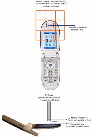
To:
{Revert to illustration
from 2001 version modified to show 15 mm unless a better illustration is
provided to show correct dimensions and preferably in B&W.}
14th Change – Annex A.2.1
Figure
A-3
From:

To:

15th Change – Annex A.2.1 Figure
A-4
From:

 The
The
To:
16th Change
– Section 4.3.2.1 Table 4-2
Leave unchanged (deferred to next revision):
Issue F – Introduction of TVC
“Incorporate TVC (test validation coil) tool into the Standard as an illustrative reference (similar to the dipole in the RF) in the T-coil Section 6 and the Annex (for development). The TVC’s intended use is as a magnetic source for measurement setup validation, to be specified as an open-sourced device. It is not intended as a substitute for Helmholtz coil calibration of the magnetic sensing probe.””
ANSI S3.22-2003 specifies a Telephone Magnetic Field Simulator (TMFS). In this proposal the ANSI S3.22 TMFS is added to the equipment list and the suggestion added to Clause 6 that it be used to validate the test setup before testing.
1st Change – Clause 2
Update the reference for ANSI S3.22
From:
[10] ANSI S3.22-1996, American National Standard, Specification of Hearing Aid Characteristics.
To:
[10] ANSI S3.22-2003, American National Standard, Specification of Hearing Aid Characteristics.
2nd Change – Clause 3.2
Add to
acronyms:
TMFS Telephone Magnetic Field Simulator
3rd Change – Clause
6.1.1.2
Add TMFS
to the equipment list:
6. Telephone Magnetic Field Simulator (TMFS)
4th Change – Clause
6.3.1
Add new
step 1:
1. A reference check of the test setup
and instrumentation may be performed using a Telephone Magnetic Field Simulator
(TMFS). Position the TMFS into the test
setup at the position to be occupied by the WD.
Measure the emissions from the TMFS and confirm that they are within
tolerance of the expected values.
5th Change – Add new
Clause D.19
Insert
new clause D.19:
D.19 Telephone Magnetic Field Simulator (TMFS)
A Telephone Magnetic Field Simulator (TMFS) such as one meeting the requirements of ANSI S3.22-2003 may be used to validate the test instrumentation and test setup for Clause 6. For convenience ANSI S3.22-2003 Figure 6 is reproduced here: